Keybonbon
Nov 20, 2022
•5 minutes
TG67 V2 Mechanical Keyboard Build Guide
The TG67 V2 mechanical keyboard kit is easy to assemble, but if it’s your first time building a mechanical keyboard, we recommend following the steps below.
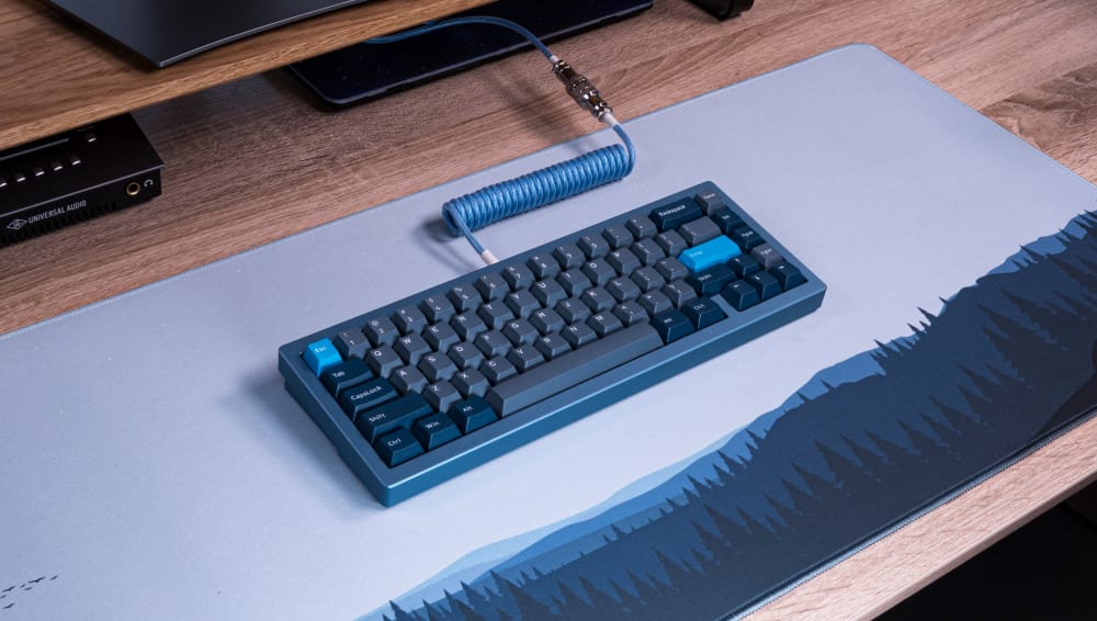
TG67 V2 mechanical keyboard in blue with PolyCaps Whale PBT keycaps
Now that you've received your TG67 V2 Mechanical Keyboard kit, it's time to build it! Follow the steps below, and reach out to our customer support team if you hit any issues.
First off, here's a full list of things that you will need in addition to what is included in the kit:
- 67 x Cherry-MX style switches (all Kinetic Labs switches are compatible)
- 67 x keycaps (all Kinetic Labs keycaps are compatible) for a 67% layout.
- PCB-mount (also known as screw-in) stabilizers, such as Durock V2 screw-in stabilizers.
The following items are included in your TG67 V2 box:
- Aluminum top and bottom case
- USB-A to USB-C straight cable
- 8 x case hex screws (pre-installed)
- Daughterboard
- JST connector cable
- 2 x daughterboard hex screws (pre-installed)
- Small brass weight (pre-installed)
- 16 large and 6 small gasket strips
- 6 rubber feet
- Hot-swap PCB with VIA support
- Polycarbonate plate (fixed layout)
- 2 layers of plate foam
- 1 layer of case foam
- 2 allen wrenches
Build Steps
Take out Hot-swap PCB from its Electrostatic Discharge Bag (EDB) and place on desk with LED bulbs facing up (the side where switches will be inserted).
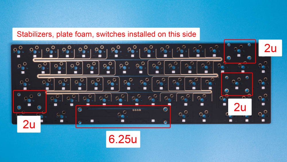
Hot-swap PCB
Place the thin layer of plate foam on top of the PCB
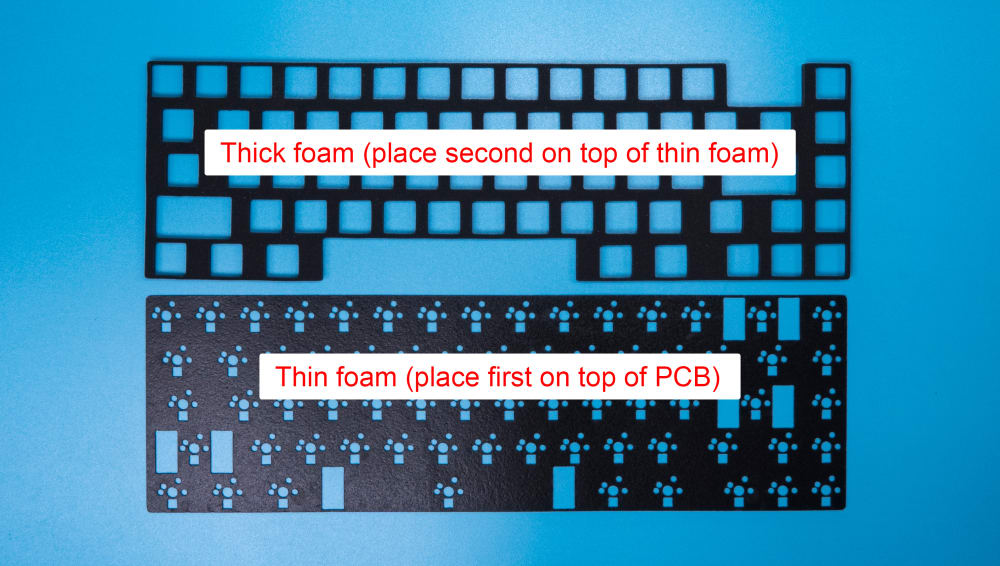
Thin and thick plate foam
Assemble your screw-in stabilizers and screw them into the PCB in the corresponding stabilizer slots.
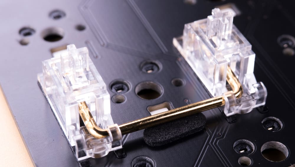
Assembled Durock V2 Stabilizers
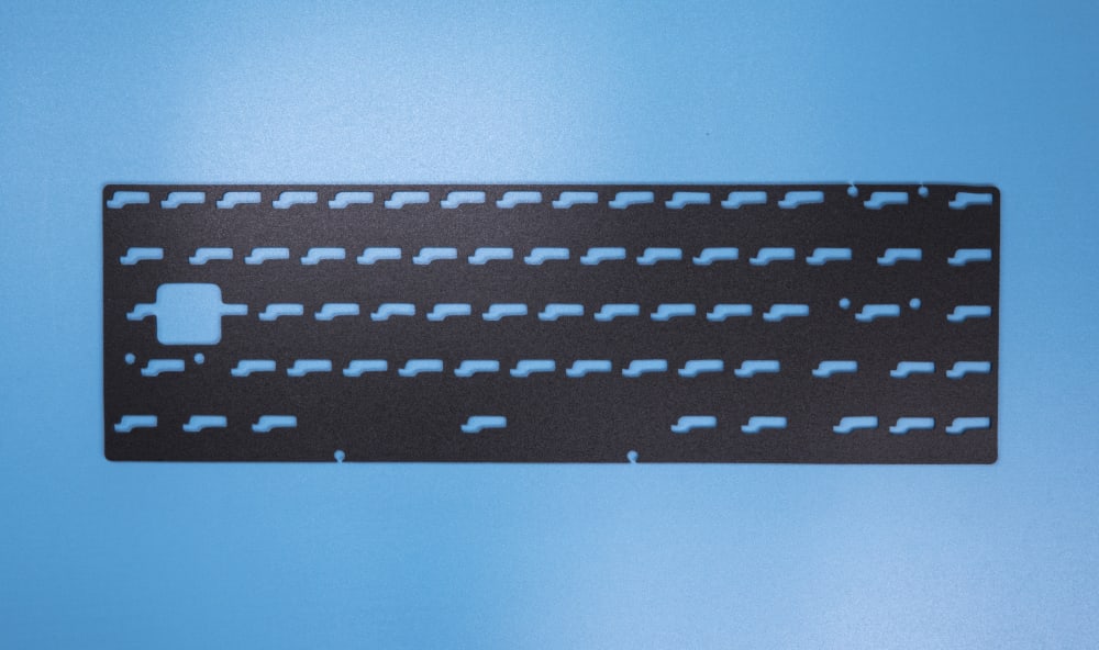
On top of the stabilizers and thin foam, install the thicker piece of plate foam (ensure the cut-outs of the foam align with the PCB and stabilizers). Place the polycarbonate plate on top of the thick plate foam.
Take your 67 switches and install them through the plate. Make sure the pins on every switch are straight and aligned with the openings on the PCB. When you install these switches, the plate must be flush with every switch. If a switch is not flush with the plate, then try to push the plate and switch towards each other until you notice they are flush.
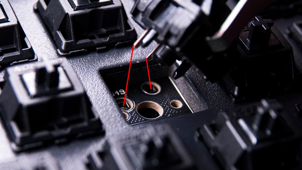
Inserting Switches into Hot-Swap PCB
Make sure the pins on your PCB are straight, otherwise the switch will not work and you will have to re-straighten the pins using tweezers.
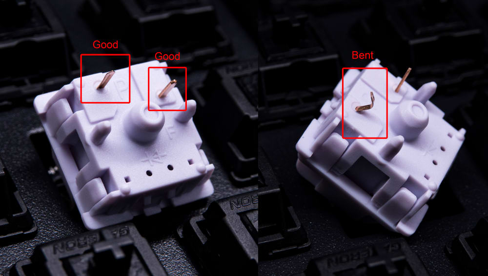
Straight vs. Bent Switch Pins
Once all of your switches are installed, un-screw your top and bottom keyboard case and take out the Gasket Strips. Align the strips to each corresponding space on both the top and bottom casings (there are long and short strips). It doesn’t have to be perfect, the strips can be little off on orientation/position as long as you fill the space. Tweezers will help in setting each strip.
Installing Gasket Strips
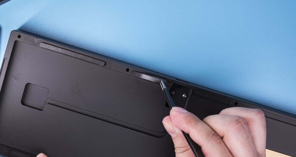
Un-screw the Daughterboard Hex Screws from the bottom casing. Next, take out the JST Connector Cable and Daughterboard from their bag and screw the Daughter Board in line with the previously removed Hex Screws. Connect the JST Cable to the Daughter Board and position the wire along the cutout spacing on the inside of the bottom casing and screw.
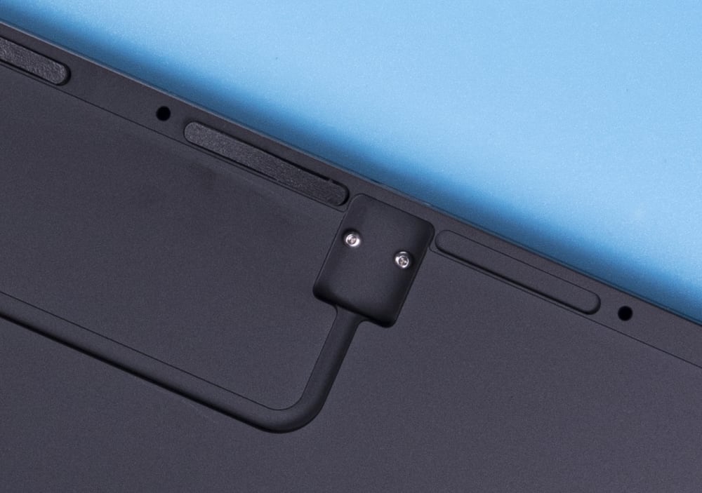
Space for Daughterboard and JST Connector
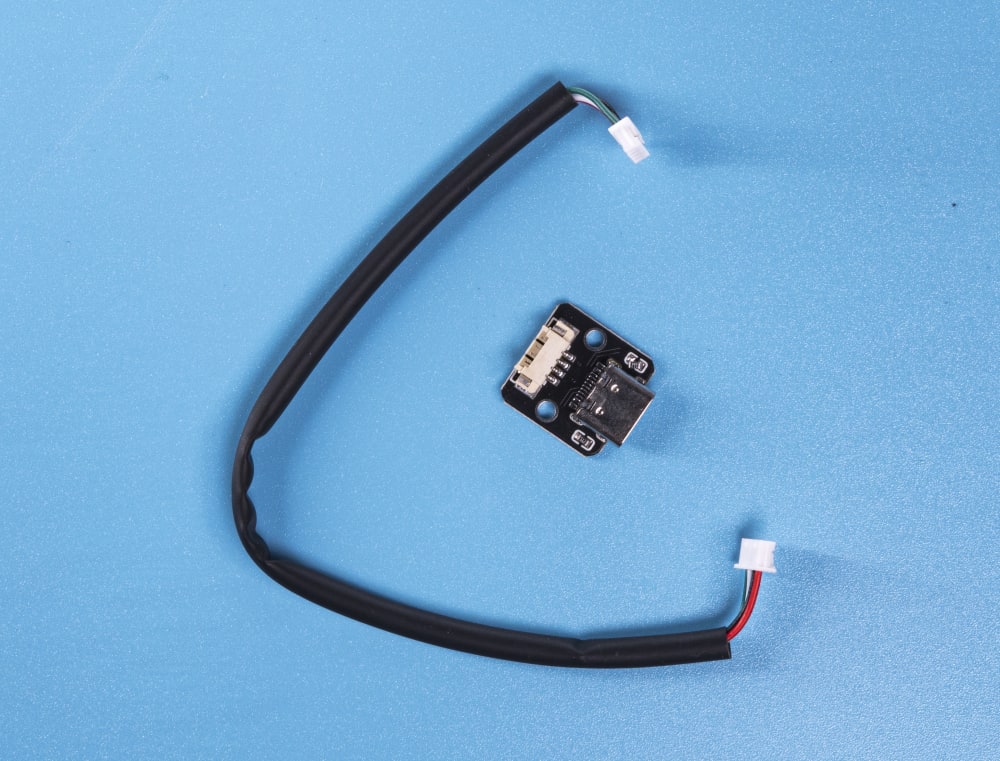
JST connector and Daughterboard
Take the layer of case foam and lay this on top of the Daughter Board and JST Cable (this is used for sound dampening within the casing). Then take the opposite end of the JST cable and connect it through the case foam to the PCB.
Case Foam
Now that the JST cable is in place and connected to the PCB, you must position the PCB/plate on top of the Gasket Strips and center the plate over the gaskets, careful not to have the plate off-center as this will cause keycap interference.
Once the PCB/plate has been centered, place the Top Casing over the PCB/plate and flip everything upside down, and screw the top and bottom keyboard cases together.
Install your keycaps, and make sure the positioning is centered around all edges to prevent keycaps hitting the sides of the case. If the PCB/plate look off-center, un-screw the top and bottom case and reposition the PCB/plate.
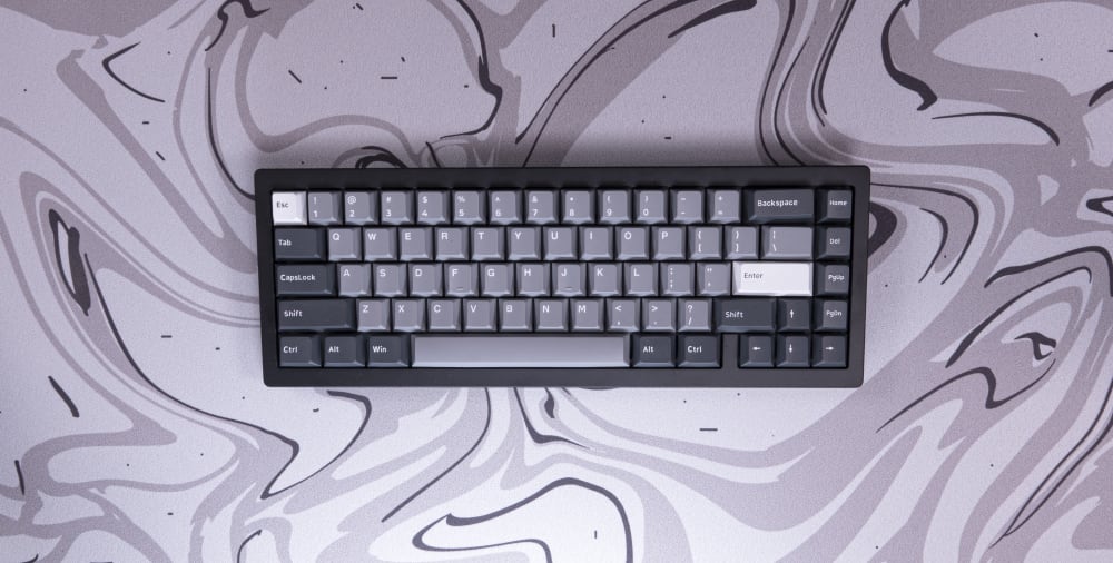
TG67 V2 with PolyCaps Seal PBT Keycaps
Connect your keyboard to your computer using the USB-A to USB-C cable.
At this point, it’s time to test your keyboard! We recommend that you use the VIA configurator. This is the same program that you can use to test individual key responses, create custom macros and remap your key bindings.
That's all! If you need help assembling your keyboard, reach out to our customer support team via live chat, e-mail, or Discord.